8-bit RISC-V Processor
A RISC-V instruction decoder implemented in SystemVerilog and synthesized on a Basys3 FPGA. Decodes all major instruction formats — R, I, S, B, U, and J-type — extracting register fields, immediates, and control signals from a 32-bit instruction word. Includes a complete testbench verifying ADD, ADDI, LW, SW, BEQ, LUI, and JAL.
datapath diagram
overview
The decoder is the first stage of a single-cycle RISC-V pipeline. It takes a 32-bit instruction and extracts all fields needed by downstream stages: register addresses, the immediate value, and five control signals that drive the register file, ALU, and memory.
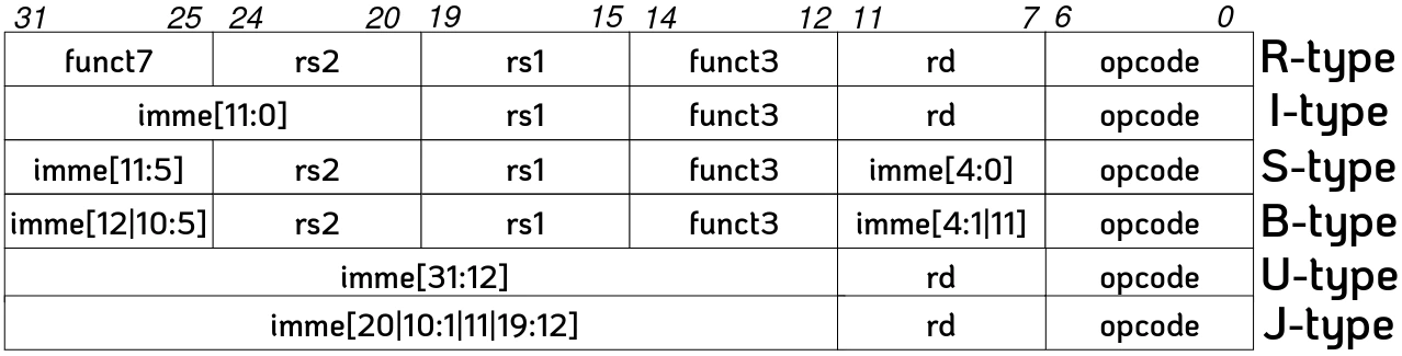
All logic is purely combinational — no clock, no state. The opcode in instr[6:0] selects which instruction format to interpret, and each format scatters its immediate across different bit fields of the instruction word.
instruction formats
| Type | Opcode | Instructions | Immediate encoding | Control |
|---|---|---|---|---|
| R | 0110011 | ADD, SUB, AND, OR, XOR | none (imm = 0) | reg_write, alu_src=0 |
| I | 0010011 | ADDI, ANDI, ORI | sign-extend instr[31:20] | reg_write, alu_src=1 |
| I (load) | 0000011 | LW, LB, LH | sign-extend instr[31:20] | reg_write, mem_read, alu_src=1 |
| S | 0100011 | SW, SB, SH | {instr[31:25], instr[11:7]} | mem_write, alu_src=1 |
| B | 1100011 | BEQ, BNE, BLT | scrambled across [31,7,30:25,11:8] | branch, alu_src=0 |
| U (LUI) | 0110111 | LUI | {instr[31:12], 12'b0} | reg_write, alu_src=1 |
| U (AUIPC) | 0010111 | AUIPC | {instr[31:12], 12'b0} | reg_write, alu_src=1 |
| J | 1101111 | JAL | scrambled across [31,19:12,20,30:21] | reg_write, alu_src=1 |
| I (JALR) | 1100111 | JALR | sign-extend instr[31:20] | reg_write, alu_src=1 |
testbench
The decoder_tb module applies seven test vectors covering all major instruction formats. Each test drives a 32-bit instruction encoding, waits 10 time units for combinational propagation, then calls a check() task that compares all nine outputs against expected values and prints PASS or FAIL with a full diff on failure.
| Test | Instruction | Encoding | Key check |
|---|---|---|---|
| R-type | ADD x3, x1, x2 | 0x0020_81B3 | reg_write=1, alu_src=0, imm=0 |
| I-type | ADDI x1, x1, 4 | 0x0040_8093 | reg_write=1, alu_src=1, imm=4 |
| I-load | LW x2, 8(x1) | 0x0080_A103 | mem_read=1, alu_src=1, imm=8 |
| S-type | SW x2, 8(x1) | 0x0020_A423 | mem_write=1, reg_write=0, imm=8 |
| B-type | BEQ x1, x2, 16 | 0x0020_8863 | branch=1, alu_src=0, imm=16 |
| U-type | LUI x5, 0x12345 | 0x1234_52B7 | reg_write=1, imm=0x12345000 |
| J-type | JAL x1, 32 | 0x0200_00EF | reg_write=1, alu_src=1, imm=32 |
links